


1 Overview
The constantly expanding network gives rise to an increasing number of failure points and adds to the complexity of configuration and maintenance. This White Paper, aiming to improve the reliability of the network and security devices, simplify management and networking, and make network easier to use, puts forward the Virtual Switching Matrix technology, or VSM, which performs virtualization of multiple L2-7 physical devices into a single logical device for management and use. The VSM technology can greatly simplify networking and improve network reliability, while facilitating configuration and maintenance. This White Paper will discuss how VSM works and how VSM helps perform virtualization of L2-7 devices, including switch, router, firewall, IPS, and application delivery.
Virtual Switching Matrix, or VSM, boasts the following advantages compared with traditional stacking:
♦ Simplify configuration and improve bandwidth utilization. Used as a device that desires no blocking of links by STP and other protocols, VSM enables cross-device link aggregation, which not only provides link redundancy, but also supports load sharing of links to make full use of bandwidth. In addition, network configuration of VSM networking is greatly simplified thanks to the elimination of VRRP and other redundant gateway protocols.
♦ Reduce operation and maintenance costs. Traditional stacking requires configuration and version upgrades on each and every device, which consumes a lot of maintenance costs. However, VSM networking enables unified management of all member devices by logging into the Master device page through any port of any member device, thereby reducing the difficulty and costs of operation and maintenance.
♦ High reliability. VSM offers high reliability, evidenced in the following aspects: 1. VSM supports cross-device link aggregation and cascading port aggregation to ensure the reliability of links and data transmission between VSM devices; 2. VSM supports multiple master redundancy in the same VSM, helping guarantee device reliability; 3. Synchronous backup of entries and sessions ensures the consistency of sessions and forwarding entries, realizing seamless switching between the main control and service boards in master/backup mode.
Applied on a wide range of products. VSM enables N:1 virtualization by supporting products of all forms from access devices to core devices, including firewall, IPS, UAG and traffic control, application delivery, router, and switch.
2 Introduction of VSM
2.1 Concept
2.1.1 VSM Member Category
Devices in the VSM are referred to as member devices. Based on functions, the member devices are classified into two different roles:
♦ Master: the master member device, which is responsible for managing and controlling the entire VSM system. All configuration information of the VSM is distributed by the Master device to all Slave devices in a unified manner. All status information of the data link layer and the upper-layer protocol state machine running in the VSM are uniformly maintained and managed by the Master device. All these information are synchronized to Slave devices.
♦ Slave: the slave member device(s), which is (are) controlled and managed by the Master. Acting as a backup device of the Master device, the Slave device(s) can also forward all the data services.
Once the Master fails, the system will automatically elect a new Master from the Slave devices to take replace of the original Master. Master and Slave devices are elected by roles. There is only one Master in a VSM, and other devices are all Slave.
2.1.2 VSM Identification
Also known as VSM ID. Each device in the VSM is identified uniquely by VSM ID, which can also be used for electing VSM member roles.
2.1.3 VSM Cascading
A VSM system is formed through VSM cascading of all member devices. Cascading boards for VSM cascading include common interface boards and dedicated cascading boards. Cascading of frame devices can be realized using 10G or 40G interface boards. In addition to interface board cascading, high-end devices also support dedicated cascading boards to achieve high-performance and non-blocking cascading. Cassette devices support cascading with 10G interfaces. When using the interface boards for cascading, some interfaces on a single board are allowed to be used for data forwarding, and others for cascading.
The ports used for VSM cascading on the cascade boards are called VSM cascading ports. VSM channels between devices are formed through VSM cascading interfaces. Automatic port aggregation is enabled when multiple physical ports are used for cascading. Cascading ports are composed of uplink and downlink ports. To realize device interconnection, the uplink cascading port of one device should be connected to the downlink cascading port of the adjacent devices.
However, due to cascading bandwidth bottlenecks, VSM networking through cascading ports may fail to realize non-blocking switching of scenarios with high performance and reliability requirements, such as data center core switching and backbone network core routing. In response, VSM supports non-blocking cascading matrix technology to improve cascading bandwidth. The VSM non-blocking cascade matrix technology adopts an independent hardware device, which is known as cascading matrix, to achieve high-speed full connection among VSM members. The cascading matrix itself has no user interface, and all its interfaces are used for cascading. The N+2 full connection networking of two cascading matrices and multiple VSM member devices is provided to ensure the reliability of cascading.
2.1.4 VSM Channel
Connection between cascading ports forms a VSM channel, which is used to transmit data packets and VSM control packets. The data packets are forwarded among member devices through the VSM channel, just like forwarding data packets among different interface boards of the same device.
2.2 Formation of VSM
2.2.1 VSM Configuration
Users are required to enable the VSM feature in the VSM Configuration, assign a unique VSM ID to each device, and configure respective uplink and downlink cascading ports for each VSM before allowing a device to join the VSM.
2.2.2 Physical Connection
♦ VSM Connection Medium
VSM supports two different connection medium: 10G/40G optical interfaces and CX4/10G electrical interfaces.
♦ VSM连接拓扑 VSM Connection Topology
VSM connection is based on the principle that the uplink cascading ports of this device should be connected to the downlink cascading ports of its peer device. The cascading topology of multiple devices is composed of the following three types:
Type 1 - Ring topology. It boasts of fast recovery in case of cascading link failure, zero packet loss, and no need to configure any protocol to prevent loops. In the event of link failure, the ring topology will switch to a chain topology, without affecting the operation of the entire VSM system.
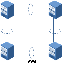
Fig. 1 VSM Ring Networking
Type 2 - Chain topology. It is a simplified version of ring topology, i.e., the VSM will split into two groups of VSMs in the event of link failure.
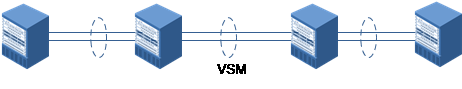
Fig. 2 VSM Chain Networking
Type 3 - Star topology. As shown below, the VSM-M (VSM-MANAGER), a system with two cascaded matrices, is used to connect the VSM-O (VSM-OPERATOR) and form another VSM system. The switching frame VSM-M is responsible for cascading and management, the cascading ports of VSM-O for connecting to the cascading matrix VSM-M, and common interface boards for service processing and traffic forwarding.
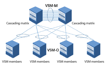
Fig. 3 VSM Star Topology
2.2.3 Topology Information Collection
Each member device needs to be aware of the topology structure of the VSM networking, which includes VSM ID of each device, the ID of uplink node and downlink node devices, and other basic information. Topology information collection occurs when a device attempts to join the VSM and delivers its own information to the VSM group. After a device receives topology information sent by other devices, it will update locally before forwarding the collected packets, which will finally be forwarded to the source member device initiating the topology information collection request. When the device receives the topology collection packets it sent from the two cascading ports, it means the device has completed its topology information collection.
Next, the device MAC address will be synchronized, causing the member devices to check their MAC addresses. In case of MAC address inconsistency between the Master and the Slave, the Slave will use the MAC of the Master instead.
2.2.4 Election of Master and Slave Devices
Devices are added to the VSM as a Slave by default. After collection topology information, a Master device should be elected out of the member devices to take charge of overall management.
Election rules of Master and Slave devices are as follows:
♦ When there is only one member device, the said device is elected as the Master;
♦ When there are multiple Master devices, the device with the smaller VSM ID in the Master devices is elected as a new Master device, and other Master devices will be restarted and then join the VSM as Slave devices;
♦ When all devices in the VSM are Slave devices, the one with the smallest VSM ID is elected as the Master, and others as Slave devices.
2.3 Management and Maintenance of VSM
2.3.1 Unified Management
VSM performs virtualization on two or more devices to realized unified management of the devices, whose configuration are exactly the same. For frame devices, the management port IP address of the Slave frame is consistent with that of the Master. When the VSM is working normally, only the management port of the master control board of the master frame is available, and the backup master control board of the master frame and the management ports of other backup frames are not available. When switching the master and backup boards or the frames, the management ports of the master control board of the new frame will becomes available, making all other management ports of other devices in the VSM unavailable. This helps ensure that the users always log in to the master frame when using the management ports to log in, making possible unified management of all devices in the VSM system.
For cassette switches or frame devices that log in to the system using management VLANs, the IP addresses of management VLANs of the master frames and the backup frames are identical. Unified management of all devices in the VSM system is enabled by having users who log in to the system using management VLANs log in to the master frames.
The VSM logs in to the management page of the Master device to manage the device in a unified manner. Configuration information of all member devices is displayed on the management page. Any configuration made on the management page will be distributed to all member devices.
When the device restarts due to manual operations or system failures, the configuration will be kept as it is. While starting up, the Slave devices will initiate a request for batch synchronization to the Master device, and then the Slave devices complete the initialization with the new configuration, ensuring that the Slave devices can be seamlessly connected to the VSM. When the VSM is running, any configuration made on the management page will be synchronized to all devices, which helps ensure that the configuration will be kept as it is if the Master device fails.
2.3.2 Adding a New Member Device
Adding a new member device to the VSM causes an UP event at the cascading port, followed by a topology change notification. The VSM system will collect topology information again, and elect a Master device when the collection is complete. If the newly added device is a Slave in the VSM, its role will remain the same in the system. If the newly added device is a Master in the VSM, then a new Master should be elected, with other Master member devices restarting and joining the VSM as Slave devices.
2.3.3 Existing Devices Logs out
During the VSM maintenance, when a device logs out of the VSM, a DOWN event of the cascading port occurs at the cascading port, followed by a topology change notification. All member devices will collect the topology information again. If the device logging out is a Slave, the roles of other member devices will remain the same in the system. If the device logging out is a Master, then a new Master should be elected among the remaining devices for managing and controlling the entire VSM system.
2.3.4 Split detection of VSM
If a device logs out of the system due to system failure and restart, then it can join the VSM system as a Slave. If it logs out due to failure in the cascading links, the VSM system will elect a new Master. In this case, there will be two groups of VSM systems in this network, with the same MAC address. This is so-called VSM split. In response, the VSM system is equipped with a VSM split detection mechanism, which will force the conflicted system to enter the Silent state, preventing it from packet forwarding and learning and service processing. In this case, there will be no conflicted VSM system in the application networking.
2.3.5 Online Upgrade of VSM
VSM supports online two-step upgrade. Firstly, isolate the backup system to perform version upgrade and configuration on the Slave devices. Once isolated, Slave devices will not process any service or forward any traffic, and only the Master can process services. Secondly, restart the upgraded Slave devices and isolate the Master. In this case, the Slave switches to a Master and takes over traffic forwarding and service processing. The isolated device will join the VSM system upon successful upgrade and restart. Services can be processed properly during the upgrade.
Specific implementation is as follows: the Slave to be upgraded is isolated, and all service interfaces are disabled. In this case, all services and data on the Slave devices will stop forwarding, and only the management port can be used for configuration and management. Next, configure the VSM ID and cascading port of the backup device, update the configuration information, and upgrade software versions (since the cascading port is also disabled, it will have no impact on the system operation). Then press the “One-click Upgrade" button to restart the Slave devices. Upon successful restart, the Slave device is still in isolated state. After notifying the Master that the upgrade is completed using an out-band channel of a management port, the Slave switches to a Master and runs normally in the network, instead of being an isolated device.
When the Master device receives a notification from the Slave, indicating that the upgrade is completed, it will switch to the isolated state, when all service ports are disabled. In this case, all services and data on the Master device will stop forwarding, and only the management port can be used for configuration and management. Next, the Slave device is still in isolated state. After notifying the Master that the upgrade is completed using an out-band channel of a management port, the Slave switches to a Master and runs normally in the network, instead of being an isolated device. During restart, the new Master device synchronizes the configuration, checks whether the software versions of the master control board and the service board are consistent, and updates with the version of the Master device if inconsistent.
The Slave will become the Master after restart, and the original Master will become the Slave. Now the online upgrade of VSM is completed.
For VSM systems with two or more devices, isolate and upgrade a Slave online first, and then notify the Master device and other Slave devices for version updates.
2.4 How the Control Plane Works
The control plane processes protocol packets by controlling member devices to realize unified management. Protocol packets include routing protocol packets, layer-2 protocol packets, DHCP, DNS and others, which are all processed by the Master device in the VSM system.
If the Master device in the VSM system receives the protocol packets, it will process the packets. If the Slave receives the protocol packets, it will not process; instead, the packets will be forwarded to the Master through the VSM cascading channel. When the Master completes the processing, it will back up relevant information to the Slave through the VSM cascading channel.
In general, the control plane is processed by the Master, which helps address the potential inconsistency of paths and states caused by separated processing of member devices.
2.5 How the Data Plane Works
2.5.1 Cross-frame Link Aggregation
Cross-frame link aggregation means that the ports on various VSM member devices are configured as an aggregation group. During configuration, the aggregation information is delivered to the Master and Slave respectively. Cross-frame aggregation provides link backup and load sharing, and the VSM supports static and dynamic cross-frame aggregation.
2.5.2 How the L2~3 Forwarding Works
Layer-2 forwarding: as the VSM works as a device, its broadcast domain includes all VSM member devices. When a VSM member device receives a broadcast packet, an unknown unicast or an unknown multicast, it will not only broadcast within itself, but also broadcast through the cascading port to other VSM member devices, which will learn these layer-2 packets. When a VSM member device receives a known packet, it looks for the layer-2 entries and sends the packet to the right egress. If the egress is not within the device itself, the packet will be sent to other devices through the VSM cascading channel.
Layer-3 forwarding: When a VSM member device receives a layer-3 packet, it looks for entries. If the search result shows there is a routing but no ARP, the packet should be reported to CPU for ARP learning. The packet processing is identical to that of a single device, if the device in question is a Master. If the device concerned is a Slave, the packets will be forwarded to the Master device through the VSM cascading channel. The Master will then deliver the entries to the Slave once it completes processing. When a VSM member device receives a layer-3 packet, it looks for layer-3 entries, and finds out the forwarding mode at the egress is identical with that of layer-2.
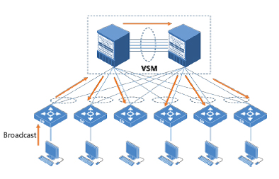
Fig. 4 VSM broadcast forwarding networking
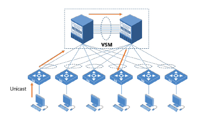
Fig. 5 VSM unicast forwarding networking
2.5.3 How the L4~7 Forwarding Works
While performing virtualization on L4 ~ 7 cassette devices, all physical resources such as CPU of all members are working in the Global mode. First, classify the received packets as per global stream. Then schedule the packets through the switching chip and cascading port to a member device for L4 ~ 7 service processing. Multiple Cloud-based scheduling algorithms are available to address the issue of two-way traffic with the same source and destination addresses. For example, the two-way traffic is matched based on source IP + destination IP address pair if no NAT is performed; or adopt different algorithms inside and outside a domain to realize the same source and destination addresses if NAT is performed. The session is backed up between all members. When a member device fails, the service traffic can be quickly switched to other devices.
When performing virtualization on frame devices, the traffic of L4~7 services is scheduled inside the VSM group through service chain technology. First define the data streams based on port, IP address, VLAN and other parameters, and then match the traffic one by one to predefined physical or virtual service modules. According to the multiple service chain modes such as online deployment and transparent deployment on the Web configuration interface to realize graphical operations for data service chain and scheduling. There are two modes of service boards in the VSM system. One is master/backup mode, in which service boards of the same type of different member devices can be configured as master/backup boards. The packets are by default forwarded to the Master service board, and will only switch to the backup boards when the Master fails. The other is Cloud-based mode, in which service boards of the same type of different member devices can be configured as virtual cloud. The packets are forwarded to a service board for processing based on cloud scheduling algorithms. Just like L4~7 forwarding of cassette devices, VSM will ensure the same source and same destination of packets, i.e., packets of the same session will be processed on the same service board.
2.5.4 Priority Forwarding
When a packet reaches a VSM member device and looks for forwarding entries, the packet will locate the physical port based on load sharing algorithm if the gateway is an aggregation port. In this case, it is quite possible that the packet should be forwarded through the cascading channel. To reduce the bandwidth usage of the cascading channel between devices, VSM allows Priority Forwarding mode, in which a packet will be forwarded through the physical port of the device from which it enters. Only when all physical ports of this device fail or in Down state can the packet be forwarded through other member devices in the VSM group.
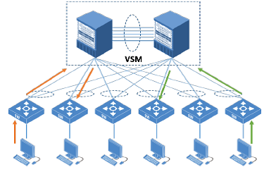
Fig. 6 VSM Priority Forwarding Networking
3 VSM State Backup
3.1 Session Backup
The sessions of each member device in the VSM system must be consistent. If a member device fails, the services it used to process can be safely switched to other member devices. When creating and changing the session of a member device, the session is backed up in real time to other devices, which makes sure that the session already exists when the traffic is switched to another device. In this way, seamless switching of service traffic can be realized. In addition, other information related to the on-site traffic, such as health check status information and dynamic routing tables, also needs to be synchronized to other devices.
3.2 Policy Backup
Policy entries on the traffic forwarding path that control the flow of traffic should remain consistent among all member devices. Such entries include service chain, packet filtering and ACL. In addition to policy configuration belonging to the device, configuration of other member devices is saved. As a result, when switching between Master/Slave devices, policy configuration on the new Master will be consistent with that of the original Master. In other words, the traffic policies in the VSM group will not be affected by the Master/Slave switchover.
3.3 Backup of Various Protocol States
In VSM group, the Master manages and maintains all slots, interfaces and resources of each member device, as well as all the data link layer and the upper-layer protocol state machine. During Master/Slave switchover, the Master will synchronize the protocol state machine in real time to each Slave device, ensuring a new Master can take over the slots, interfaces and protocol computing in running. In this way, the new Master is capable of receiving the running status information of each protocol and guaranteeing the continuous operation of protocol state machine.
4 VSM Networking Application
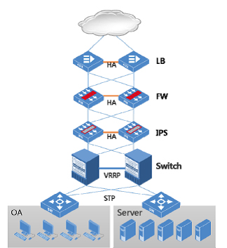
Fig. 7 Traditional Serial Networking
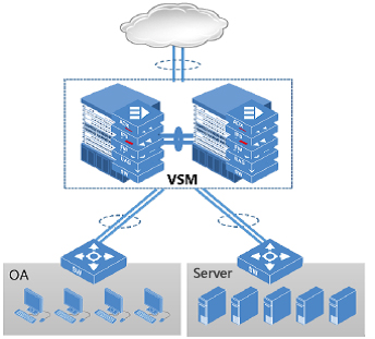
Fig. 8 VSM Networking
As shown in Figures 7 and 8, the DPX board hybrid VSM networking boasts the following advantages compared with traditional networking, security, and application delivery networking:
♦ Simplified Networking
Dual-system hot standby in traditional networking is realized by using VRRP gateway redundancy protocol or routing. But in VSM networking, load sharing on packets are performed to achieve dual-system synergy and simplify the networking without using the VRRP technology.
♦ Flexible Scalability
VSM networking can flexibly expand system services by adding various service boards of the same type.
♦ Improved Protection
For example, the IPS device may fail to detect a complete flow of traffic due to the different routes of two IPSs in the network. As a result, attacking traffic might find its way into the internal network. In VSM networking, the complete data traffic can be detected and protected to block the attacking traffic.
♦ Simplified Device Management
In tradition deployments, each device is managed independently, thus raising the maintenance cost. While in VSM, all frames and service boards are equipped with a unified management IP and a management interface, allowing all configuration and management to be completed in one stop.


